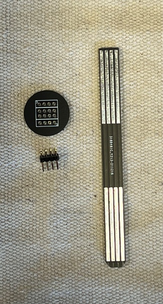
1. The parts of the PCB Stick
The PCB Stick has three parts. The stick, a double row header,
and a disc that the signal mounts to.
|
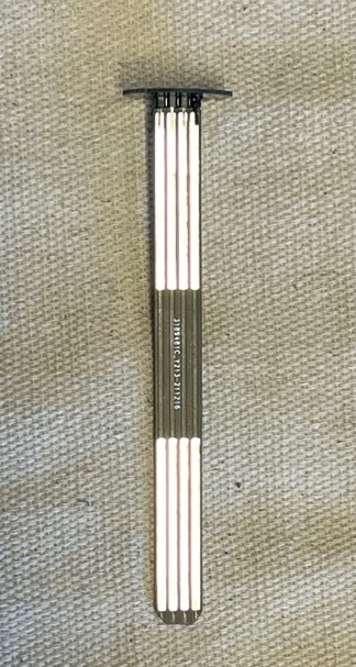
2. The PCB Stick Assembled
This is what the assembles PCB Stick looks like.
|
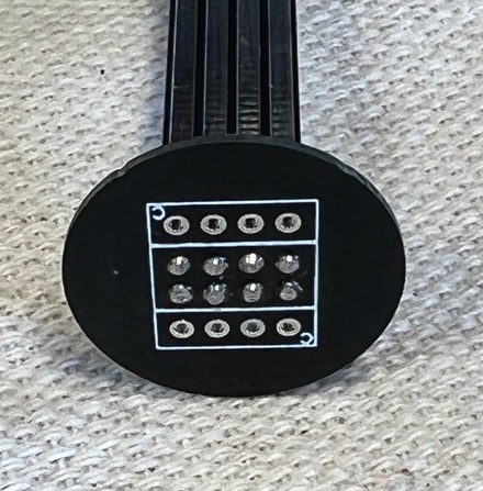
3. Top of the PCB Stick
The top of the PCB Stick is a 3/4" round disc that the signal
is mounted to. We recommend some kind of glue like 5 minute
epoxy. There are 8 solder pads for 4 wire from each head. The
fine wires are kept between the round disc and the bottom of
the signal, protected from getting snagged.
NOTE: This disc us upside down, ERROR
|
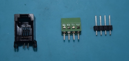
4. Connection Options
There are three connector options for connecting your signal
driver to the Signal Mount. First there is a Modular 4P4C Jack
(J3 and J4) for plug and play ease using a Big Ditch Designs
Signal Driver. We included a 0.10" (2.54mm) spaced set of solder
pads to take a pin header or a screw terminal. A fourth option
would be to solder wires right to the board on the pads.
|
5. PCB Stick Assembly Step 1
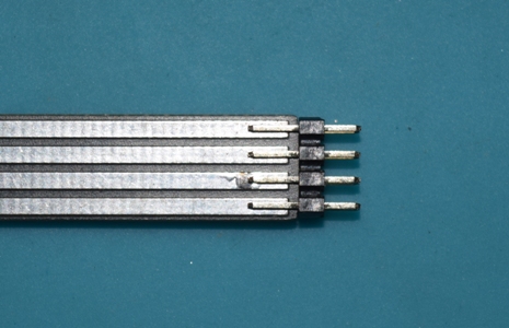
Place the double row header on the top of the PCB Stick.
The long pins onto the stick is preferred but not required.
Solder both sides.
|
6. PCB Stick Solder Jig
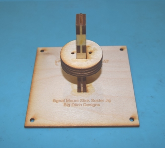
We make a soldering jig to help hold the PCB stick while
soldering the parts onto it. The double row header it stays
in the stick and it not bad. But the next step is to solder
the PCB disc onto the top of the stick. Placing the stick in
the jig makes it easy to keep the PCB disc square to the stick.
If the round is not square to the disc, your signal will lean.
|
7. PCB Disc Placement
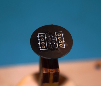
One side of the PCB Disc has one square on it, the other
side has two squares on it. The side with the one squares goes
up. See the image below. Place the stick in the jig, place the
PCB Disc on top of it. Be sure the disc is level and solder
in place.
You can use the jig to hold the assembled stick while you
solder the signal wires onto the stick. Then glue the signal
onto the stick, watching to be sure the signal is vertical.
NOTE: This disc is upside down.
|
8. Laser Cut Base Parts
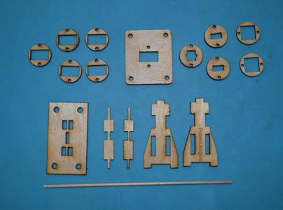
On the top are the laser cut rings, the bottom are the base
pieces. There is also a small dowel included.
|
9. Main Bass Assembly
Gather the 5 main base pieces.
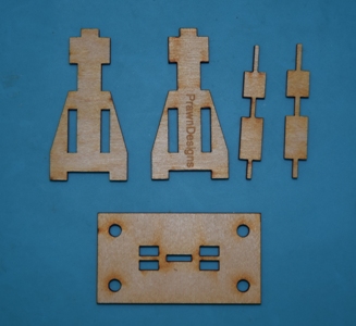
Do not use any glue yet, place the two smaller spacer piece
into one of the sides.
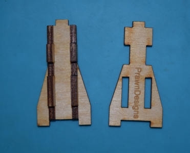
Place the second side onto the assembly.
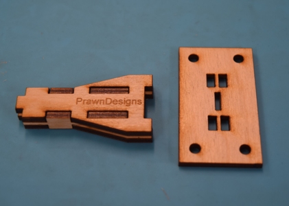
Place the side assembly onto the bottom.
It is very important that you do not get any glue in the
center slot formed by the sides and spacers. I do not put any
glue on these pieces. I put a small amount on the bottom before
I place the sides assembly onto it.
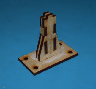
I use a q-tip to mop glue around the base.
Again it is very important to not get any glue in the center
slot.
Let the assembly dry.
|
10. Base Rings
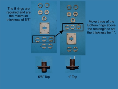
There are 10 round rings and one square ring. By changing
the order of the rings the mount can be adjusted in 1/8" (really
closer to 0.12") steps to accommodate different thickness of
module tops (bench work). The system is adjustable between 5/8"
and 1 1/4". When measuring your bench work thickness remember
to include the thickness of your scenery material where the
signal will be mounted.
Note: Two of the rings (2 and 5) are a little fragile and
sometimes break, so I include some spares rings, not shown in
the image.
Ring Markings
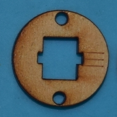
The rings are not all the same. The rings are marked (numbered)
on one side with small score marks (lines). These indidate which
ring is which. The top five rings IIIII, IIIII, IIII, IIII,
III are required. They must be in the correct order to have
room for the top of the stick to fit into the base. Rings marked
II can go above or below the large square ring marked I. This
is to adjust for the thickness of your benchwork.

Ring Assembly
You can do a dry fit without glue to check the height of
the stack to your bench work, the fit on the dowel is very snug.
Be careful, you can break the rings putting them together and
taking them apart.
In this example I am assembling a mount for module top (bench
work, sub-roadbed) that is 5/8" thick. This measurement is the
distance from the of the module top to where you want the base
of the signal to sit including scenery material.
Take the small dowel and cut two pieces about 2" long. Stack
the discs, in order, onto the two dowels placing a small amount
of glue between each disc. From top to bottom the discs go in
this order.
IIIII, IIIII, IIII, IIII, III, I, II, II, II, II, II
(two 5, two, 4, one 3, one 1, five 2)
NOTE: the image below only shows four number 2 rigns, but
5 are used, plus one extra 5 and 2 ring.

After the first set of discs put the rectangle on. This is
the mounting plate, it will be screwed to the bottom of you
sub-roadbed.

In order place the rest of the rings onto the dowels.
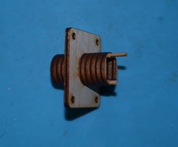
NOTE: The arangment shown is for 5/8" thick bench work, sub-roadbed,
if you need it thicker, move the number 2 rings up to between
the Number 1 (rectangle) and number 3 ring one at a time to
get the desired depth up to 1 1/4" |
11. Put the Rings on the Base
This stack is now placed onto the base. I use a q-tip to
mop glue onto the sides of the base and slip the rings down
on. Be sure to seat the rings all the way down onto the base.
The first of the top rings keys down onto the base, look down
into the top to ensure it is seated all the way down.
In this example I made the shortest mounting base possible
with only the 5 required rings on the top. You can see that
the 5 required rings make a mount for 5/8" thick sub-roadbed.
This measurement includes any scenery (dirt, ballast, etc.)
that will be under the signal base.
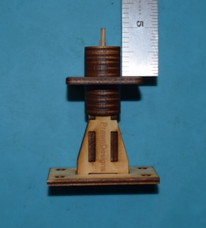
When the glue dries use a knife to trim the dowels flush.
|
12. Thicker Bench work / Taller Mount
To make a mount that is taller, move one or more of the rings
from the bottom to the top of the rectangle piece.
The one on the left is setup for 5/8" the one on the right
is setup for 1".
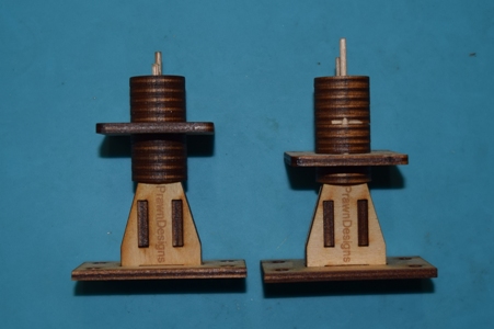
|
13. Mounting the Bottom PCB
You should have soldered in your resisters and connectors
(Modular 4P4C, pin header, or a screw terminal) you choose to
use. The picture below does not have the connectors or resisters
installed on the Bottom PCB
The part you will need are:
The Bottom PCB (with resisters and connectors soldered on)
(4) #4-40 1/2" Machine Screws
(4) #4 washers
(8) #4-40 nuts
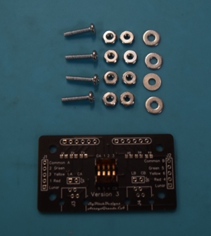
|
14. Install Machine Screws
Install the 4 machine screws from the side with the components
and put a nut on the back of each screw. Tighten the nuts down
snug.
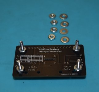
|
15. Mount PCB on Base Assembly
Place the Bottom PCB onto the Main Base assembly and place
one washer and one nut on each or the mounting machine screws,
do not tighten these yet, leave them loose.
Note, there will be some play this will allow the Bottom
PCB to move around a little.
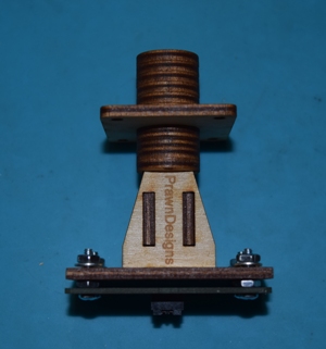
|
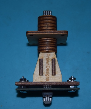
16. Align and Tighten the Bottom PCB
Place a PCB Stick into the Main Base assembly from the top.
Use it to align the Bottom BCB, then tighten the nuts. You should
be able to remove and insert the PCB Stick with just a little
force. Loosen, realign, and tighten the nuts if needed.
|
17. Connecting Your Signal
At this point you should have:
- The Main Base assembled for your thickness of bench
work where you will be installing the signal.
- Your resisters installed on the Bottom PCB
- Your choice of connectors installed on the Bottom PCB
- The Bottom PCB aligned and installed on the Main Base
- The PCB Stick, double row header, and PDB Disc soldered
together.
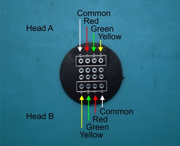
Time to connect your signal to the PCB Disc on the PCB Stick.
Solder the signal wires from your signal head to the corresponding
solder pads on the PDB Disc.
|
18. Test and Glue Signal to PCB Stick
You should test your signal head before gluing your signal
to the PCB Disc.
This system is designed to have the flat side of the PCB
Stick facing the track, see the image below.
After you have tested your signal, tuck the extra wire up
into the base and glue the signal base onto the PCB Disc.
Signal NOT included.

|
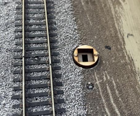
19. Mount the Main Base Assembly
The System requires a 3/4" hole in your bench work. Bring
the Assembly up from the bottom and screw it into place. Ensure
that the PCB stick is aligned correctly.
|
20. Removing a Signal
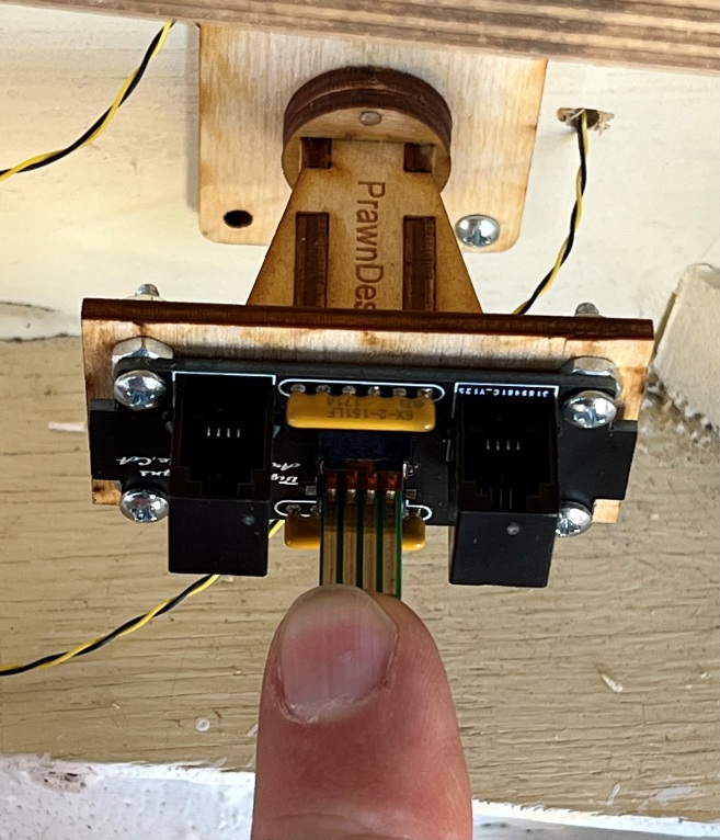
Place your signal on the PCB stick into the mount and press
down gently on the PDB Disc to set it into the base. To remove
the signal, press up in the bottom of the PCB stick to lift
the signal slightly out the layout. Then lift the Signal out
by the PCB Disc.
|
